
From one rotor to a wake-optimised farm.
A multi-megawatt turbine modelled where aerodynamics, drivetrain dynamics and control meet — the Cp(λ) surface, a two-inertia drivetrain, region-2 MPPT and region-3 pitch control, and turbulent loads — then scaled out to a farm where wake interaction is optimised away for 18% more annual energy. The drivetrain also lives as a runnable acausal .djl over a custom rotational domain.
Aerodynamics, control, and a whole farm.
Each subsystem is its own runnable notebook, building from a single rotor's coefficient curve up to a wake-coupled farm layout.
Rotor aerodynamics
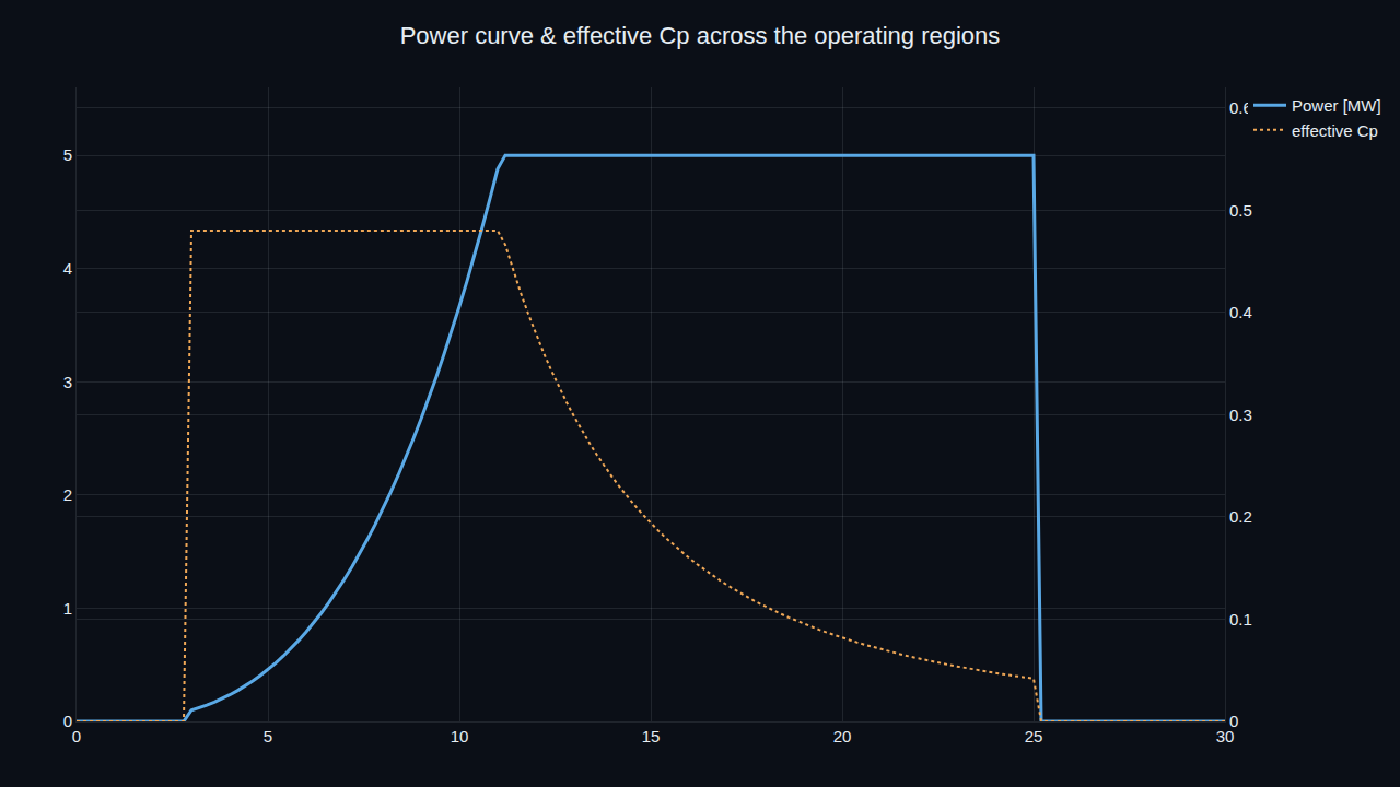
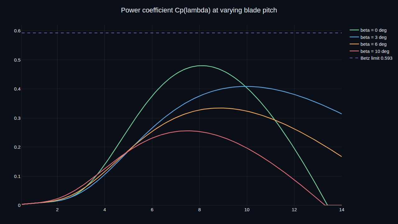
The power coefficient Cp(λ, pitch) and the full power curve — peak Cp ≈ 0.48 at a tip-speed ratio of 8.1, 81% of the Betz limit, across cut-in, rated and cut-out.
Drivetrain
A two-inertia drivetrain — rotor, a compliant low-speed shaft, gearbox and generator — spins up under a K-ω² law to 12.3 rpm and re-settles cleanly after a wind step.
MPPT control
A wind-sensorless K-ω² torque law holds the tip-speed ratio around its optimum through varying wind, capturing near-ideal power in region 2.
Pitch control
A PI pitch loop feathers the blades in region 3 to hold rated power through a +5 m/s gust with only 0.4% overspeed.
Turbulent loads
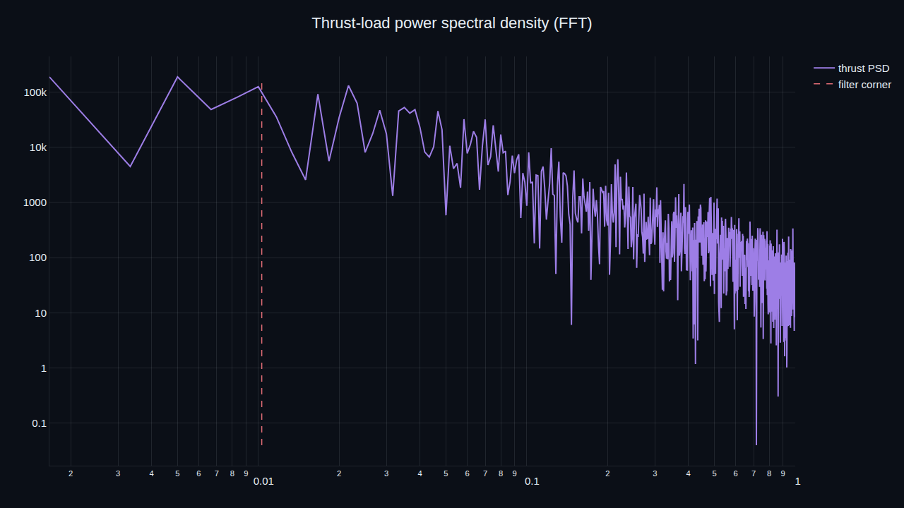
A Dryden-like turbulent wind field (TI ≈ 0.14) drives the rotor to a ~736 kN thrust load, with a low-frequency-dominated load spectrum from the FFT.
Farm & wake
A Jensen wake model with a CMA-ES layout optimiser lifts wind-rose annual energy 18% over a naive 4×4 grid — the optimised 16-turbine farm on a map.
A drivetrain on a brand-new physical domain.
The two-inertia drivetrain is a runnable acausal .djl — aerodynamic torque into a rotor inertia, through a compliant shaft and a step-up gearbox, into the generator's torque-control brake. It is built on a custom rotational domain (angle as the potential, torque as the flow) that doesn't ship in the block catalog — defined inline in a few lines and solved by the same kernel that handles electrical and mechanical networks, with no engine changes. It spins up from 1.0 to 1.49 rad/s to its region-2 torque balance, about 6 MW. The same acausal kernel models fluid power, rotational mechanics, or any domain you can write a connector for.
Every claim is a number you can re-run.
The notebooks are gated on worker-verified results, and the drivetrain .djl is confirmed solving through the production canvas engine.
| Result | Detail | |
|---|---|---|
| Peak power coefficient | 0.48 | 81% of Betz |
| Rated power held through gust | +0.4% overspeed | PI pitch |
| Turbine annual energy | 20.3 GWh/yr | CF 46% |
| Farm annual energy | 295 GWh/yr | CF 42%, 9% wake |
| Wake-optimised AEP gain | +18% | vs 4×4 grid |
Design-grade aero, control and wake.
Aerodynamics is a Cp(λ, pitch) coefficient model, not a blade-element-momentum or CFD rotor; the drivetrain is a lumped two-inertia model; the wake is the analytic Jensen model, not a high-fidelity wake simulation. Turbulence is a Dryden-like spectral field. That is the fidelity wind-farm design needs first: sizing the rotor and drivetrain, tuning the torque and pitch controllers, bounding turbulent loads, and laying out the array so wakes cost the least energy — on your own site wind rose, before a CFD campaign or an aeroelastic model.
Model your own turbine and site.
Book a walkthrough and we'll drop in your rotor, drivetrain and site wind data and run the control, loads and farm-layout studies live.