
Will it break, and how does it shake?
Finite-element analysis answers the two questions every structure has to pass: how much does it deflect and where does it break under load, and how does it vibrate. You discretize the part into thousands of small elements, assemble a giant stiffness matrix, and solve — for displacement and stress, or for the natural frequencies and mode shapes that come out of an eigenvalue problem. It's the most widely used simulation tool in engineering (ANSYS Mechanical, Nastran), and this program builds it from the element up — validated, at every step, against the formulas you can check by hand.
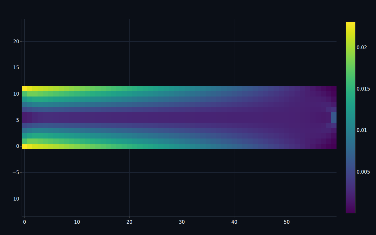
Where the material is working hardest.
Load a cantilever at its tip and the stress isn't uniform — it concentrates at the clamped root, on the top and bottom surfaces where the bending is greatest, and falls to nothing at the neutral axis and the free end. The finite-element solver computes the full von Mises stress field that shows exactly this, and the tip deflection it predicts lands within 0.58% of the Euler–Bernoulli beam formula. The field tells you where to add material; the agreement tells you to trust it.
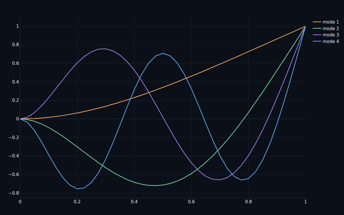
Every structure has notes it wants to ring at.
Beyond static strength, a structure has natural frequencies — the rates at which it wants to vibrate — and a mode shape for each. Find them by solving a generalized eigenvalue problem on the stiffness and mass matrices, and out come the resonances you must keep away from a bridge's traffic or an engine's vibration. On a cantilever the computed frequencies match the analytic values to four decimal places, and the mode shapes are the textbook bending forms.
Holes, corners and slender columns.
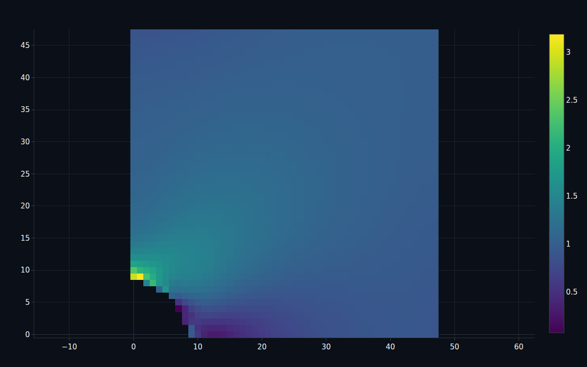
Real parts fail at their details. A hole in a loaded plate triples the local stress — the stress concentration factor of about 3 that the analytic Kirsch solution predicts, and that the solver recovers as the hole shrinks. A slender column doesn't yield, it buckles, at the Euler load the solver matches to the digit. And an L-bracket's re-entrant corner is a stress riser that sets its factor of safety. These are the features that decide whether a part survives.
From a stress field to a factor of safety.
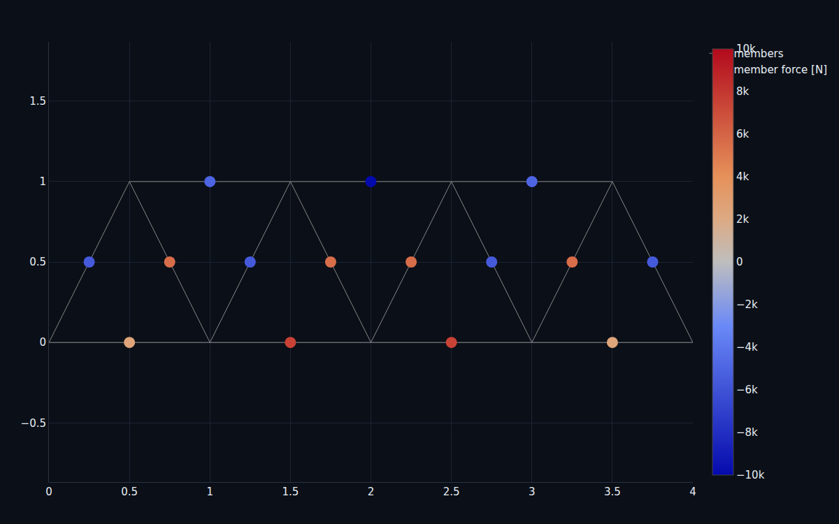
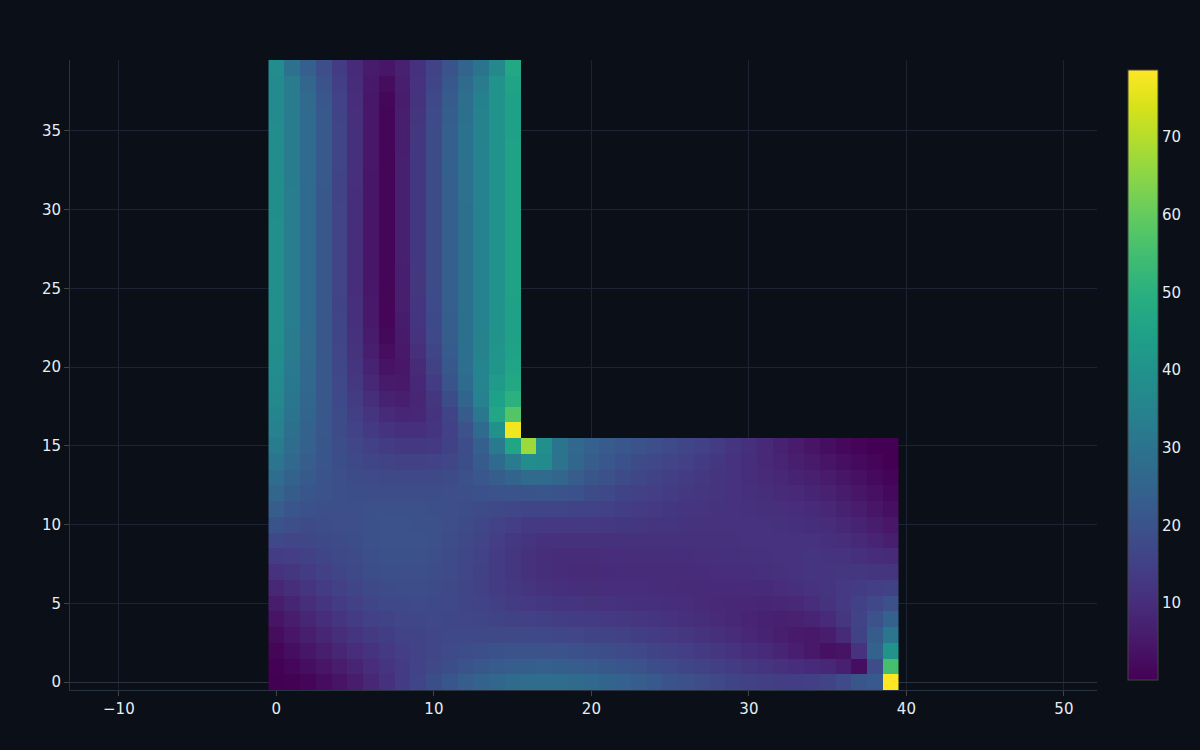
Put it together on a real component — an L-bracket clamped along the top with a load on its arm. The solver finds the peak stress at the re-entrant corner, and dividing the material's yield strength by it gives the factor of safety, the single number a design review turns on. Sweep the load and you read off the allowable: how hard you can push the part before the safety margin runs out. That's FEA doing its actual job — turning a geometry and a load into a go/no-go.
Every number re-derived at sign-off.
The V&V notebook rebuilds the solver from scratch and re-derives each requirement against closed-form theory, printing a PASS/FAIL board.
| Result | Requirement | |
|---|---|---|
| Cantilever deflection vs beam theory | 0.58% | R-01 < 3% |
| Modal frequencies vs analytic | 0.0001% | R-02 < 0.1% |
| Mesh convergence | monotonic | R-03 |
| Stress concentration factor | 3.3 → 3 | R-04 |
| Buckling load vs Euler | 0.00% | R-05 < 1% |
A real solver, at teaching fidelity.
The deliverable is ten notebooks and the dossier — a discretized structural field with an eigenvalue problem, not an acausal lumped network, so there's no custom block or canvas. It uses Q4 plane-stress and Euler–Bernoulli beam elements, linear-elastic small strain, a dense direct solver at modest mesh sizes, and centre-point stress recovery — no contact, plasticity or large deformation. What the program proves is the capability the portfolio most lacked: finite-element structural mechanics, both static stress and modal vibration, validated against closed-form theory at every step — and it's the same FEM solver the topology-optimization flagship runs in its loop, the structural-field counterpart to the CFD and electromagnetics field solvers.
Analyze your own structure.
Book a walkthrough and we'll mesh your part, apply your loads and supports, and run the stress, modal and buckling studies live.